May 29th, 2011
Transistors are difficult to explain. Search the web and you’ll find lots of attempts to explain how transistors work, but the explanations don’t make much sense. There are two types of explanations: engineering explanations, which make no attempt to explain what’s going on inside a transistor; instead, they just tell you what the external behavior is. As far as the engineering explanations care, transistors are magic black boxes that do wonderful things.
The second kind of explanation is the physics explanation, which is totally mind-boggling. The problem with the physics explanation is that it gets into all sorts of messiness with electrons, which are negatively charged, moving one way, and “holes”, which are in effect positively charged, moving the opposite way, and all this positive and negative stuff moving one way or the other can be confusing. So I’m going to take a different tack. My explanation is still a physics-type explanation, but I’m going to simplify some of the positive-negative complexity.
The first thing you need to understand is the idea of “charge carriers”. These are just things that have an electric charge, either positive or negative, and can move. In fact, negative charge carriers are electrons and positive charge carriers are “holes”, but we won’t get into that confusing terminology. Just think in terms of negative charge carriers and positive charge carriers. Each charge carrier carries exactly one unit of charge.
The next thing you need to know is the basic rule of electricity: like charges repeal each other, and opposite charges attract each other. In other words, positive charge carriers are repelled by other positive charge carriers (and will try to move away from them), and positive charge carriers are attracted by negative charge carriers (and will try to move towards them).
So here’s what a copper wire looks like when we think this way:
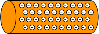
It’s just a chunk of metal with lots of negative charge carriers floating around freely. There are positive charges in there, too, but they’re nailed down to the copper atoms in the wire. The negative charge carriers are only loosely tied down, so they can move around easily.
Next, let’s turn to a battery. It’s just a device whose internal chemistry sucks negative charge carriers into one of its two poles. It doesn’t push anything to the other pole, but since negative charge carriers were sucked to one side, the other side has a shortage of negative charge carriers, and so is in effect positively charged. Positive attracts negative, so the negative charge carriers on one side are attracted toward the other side — but the battery is built so that they can’t do that. They need to find another way. If we connect a copper wire from one side of the battery to the other, they’ll push the nearby negative charge carriers inside the copper wire away (remember, like repels like), which will cause other negative charge carriers to push, and so on throughout the wire, until the negative charge carriers at the end of the wire get pushed onto the other pole of the battery, which does the job. This flow of negative charge carriers is called an electrical current. The amount of current that flows depends on how many negative charge carriers the battery has pushed over to one side. The more crowded the negative charge carriers, the higher the pressure to push through the copper wire. This pressure we call voltage.
BUT! (This is important!) It’s NOT the case that the negative charge carriers at one end of the battery flow through the copper wire to the other side of the battery. Instead, the negative charge carriers at that end of the battery push the nearest negative charge carriers in the wire, which push the ones near to them, which push the next, and so on. The wire is not like a hollow pipe that the current flows through; it’s like a line of bumper cars; if you push the car at one end, it pushes the one in front of it, and the process continues until the bumper car at the end is pushed. This is an important point; don’t forget it!
Now let’s consider a chunk of pure silicon. It has no charge carriers at all; they’re all locked down in the atoms of the silicon. Sure, there are plenty of electrons and such, but they’re held tightly by their silicon atoms. Thus, if we connect a battery to the silicon, there won’t be any charge carriers to respond to the negative charge carriers in the battery. No current flows. Nothing happens. Thus, pure silicon is called an insulator, while copper is called a conductor.
But now it’s time to get into some magic. Suppose that we manufacture some silicon that isn’t exactly pure. It’s almost pure, but we deliberately mix in a special contaminant. If we do the mixing process with just the right kind of contaminant, it turns out that a few of the negative charge carriers in the silicon are set free. They can wander freely around inside the chunk of silicon. But here’s the wild part: we can also use a different kind of contaminant to manufacture the impure silicon, and with that different contaminant, we liberate a few positive charge carriers. In other words, we can manufacture two different kinds of impure silicon: stuff with a few free negative charge carriers, and stuff with a few free positive charge carriers. Here’s my little sketch of what they look like:
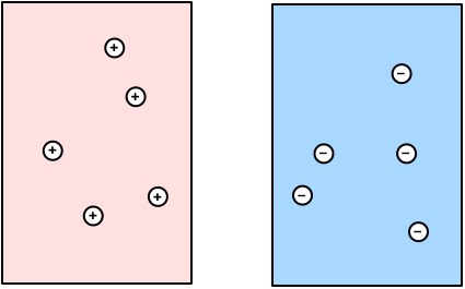
It’s really important to realize that there aren’t many free charge carriers in these impure silicon; maybe one atom in a billion has a free charge carrier. It’s not at all like copper, where every atom has a free charge carrier. So this impure silicon isn’t really a conductor like copper. But it does permit some electrical current to flow, so it isn’t an insulator, either. We call it a semiconductor, because it permits some current to flow.
Now, what do you think happens when we stick these two pieces together, like so:
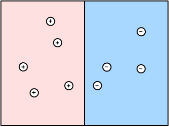
Remember that positive attracts negative. This only works for charge carriers that are close together; if they’re far apart, the attraction is weak. Therefore, the nearby charge carriers are attracted to each other:
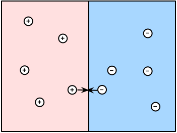
Of course, when a positive charge carrier meets a negative charge carrier, they cancel each other out, leaving no charge carriers behind. Since all the charge carriers near the boundary zone meet each other and cancel each other out, we end up with something in the middle called a depletion zone:
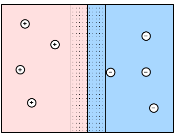
Inside the depletion zone, there are no free charge carriers. Ergo, the depletion zone is an insulator; charge carriers can’t move through it, so no current can flow through it.
Now let’s try something new: what if we hook up the copper wires from the battery to both sides of our two-part device, like so:
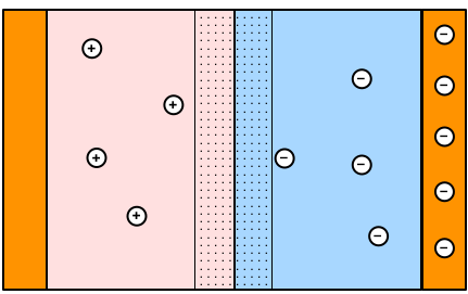
The negative charge carriers on the right side will repel the nearby negative charge carriers, which will move towards the depletion zone. The negative charge carriers that reach the depletion zone will push into it and all the way to the pink half of the depletion zone. There they will encounter some of the positive charge carriers that had previously been caught and locked down; they’ll attract the positive charge carriers away and thereby liberate them. However, if the voltage (pressure of the negative charge carriers) is small, the negative charge carriers won’t penetrate far into the depletion zone, and we’ll get a shrunken depletion zone, like this:
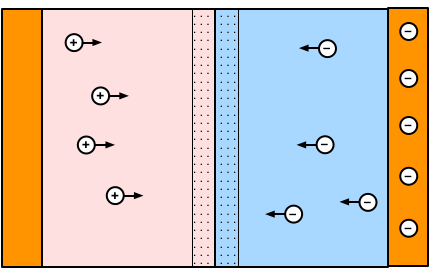
But if we increase the voltage from the battery, that increases the pressure on the negative charge carriers, and they’ll push all the way through the depletion zone, crushing it into nothingness:
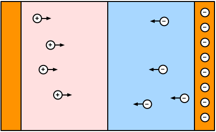
This situation is completely different: now there are free charge carriers all the way through this semiconductor pair. Since the charge carriers can move freely, current flows. In other words, our device prevented current flow so long as the voltage was low, but if we make the voltage large enough (about half a volt, typically), suddenly current can flow freely. Isn’t that cute?
Cute, yes, but not terribly useful. But now let me show you something more interesting. Suppose that we reverse the polarity of the battery connections, like so:
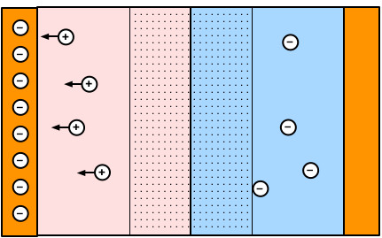
Now the negative charge carriers from the battery are connected to the side that has free positive charge carriers. They are all attracted towards the negative charge carriers and AWAY from the depletion zone. With fewer free positive charge carriers to inhibit it, the depletion zone actually expands! The semiconductor pair is an even stronger insulator than it was before.
Think about this for a minute. If we hook up the wires one way, current will flow; but if we reverse the connections, current will not flow. This is a one-way device; it permits current to flow in one direction only. A copper wire permits current to flow in either direction, but this thing permits only one-way current. This is a much more useful device; it is called a diode, and there are lots of diodes in most electrical devices. They act like one-way valves for current.
OK, now you’re ready to see a transistor. A diode has two layers, and a transistor has three layers, like so:
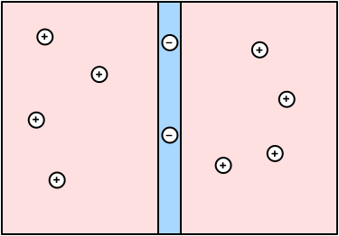
Notice that the middle layer is very thin; that’s no accident — it’s crucial to the operation of the transistor. At first glance, you’ll wonder what this arrangement could possibly accomplish. It looks like two diodes fused together in such a way that current could never flow in any direction. But if we hook it up just right... let me show you. Here’s the transistor with its depletion zone all set up. Note that the depletion zone completely covers the middle layer:
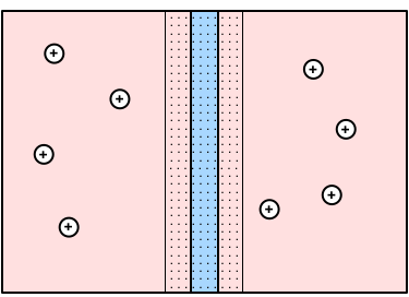
Now suppose that we hook up wires to the transistor like so:
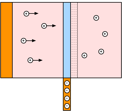
This is really just a diode turned sideways. The depletion zone on the left side of the transistor is squashed away, which will permit current to flow between the left side and the wire to the middle. This is just another example of a diode at work. But now let’s get sneaky: we add ANOTHER wire to the RIGHT side of the transistor, like so:
Because the middle layer is very skinny, the positive charge carriers can’t squeeze through very quickly; they pile up inside the middle zone. Meanwhile, the positive charge carriers on the right side are attracted to the negative charge carriers in the copper wire on the right side:
Without those positive charge carriers in the right side repelling the positive charge carriers in the middle piece, those positive charge carriers can push across the depletion zone and collapse it:
So now current can flow through the right side of the transistor. But here’s the big deal: because the middle piece is so skinny, not many charge carriers can move through it, but lots of charge carriers can move to the right side. In other words, we get lots more current going through the right side than the middle.
Think of this as a line of people waiting to get into a popular movie. The line for the popular movie is long and is moving slowly, so lots of people are getting tired of standing in line (inside the blue zone). They notice that there’s another movie with no line at all. A lot of those people will jump out of the line and go to the second movie.
Here’s the really neat (and terribly important!) part: if we reduce the voltage on the wire going to the middle piece, reducing the pressure on the charge carriers, then we’ll get fewer charge carriers moving into the middle piece:
And with fewer charge carriers in the middle piece, there are fewer charge carriers to jump across to the right side. This is sensational! It’s an amplifier: a tiny current on the middle piece controls a much larger current on the right side. Or it can be a simple switch: if there is no voltage at all on the middle piece, no current at all will flow to the right side, but if there’s enough voltage on the middle piece, then lots and lots of current will flow to the right side. A tiny current can be used to switch on or off a much larger current.
And that is how transistors work.
