Patton Versus Rommel is not my best work, but it does have some interesting geometric techniques for its AI. In this article I shall try to explain the ideas behind the AI.
Figuring the Line
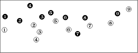
A standard problem in computer wargames is figuring the line. The military units of each side line up along the frontline and duke it out, attempting to penetrate the enemy line and hold their own line. The first task for the AI to perform is to figure out where the line is. This is not so easy a task. Consider the following map:

There are several difficult judgements to make about this line. For example, should the black line be drawn 1-2-3-5 or should it include unit 4? That is, should unit 4 be treated as a member of the front line or a reserve unit? How far back or forward must unit 4 be to be excluded or included?
Black unit 7 provides us with another quandary. Is it part of the black line or should it be treated as a unit cut off behind enemy lines? We could draw the black line as 5-6-7-8- 9 or 5-6-8-9. Which is better?
One would expect that the line would be built according to the proximity of units. That is, the line is a sequence of units in proximity to each other. This creates problems of its own. For example, white unit 2 is closer to white unit 3 than white unit 5; this would pull the line through 3 and on to 4. Then the line would have to double back on itself to get back to white unit 5. Obviously, proximity alone is an insufficient criterion for building the line.
I tackled these problems with a sequence of algorithms. The first algorithm draws not a line but a polygon. The polygon is constructed as follows: start with an arbitrarily chosen unit; call it UnitA. Choose the closest unit and draw a line to that unit; call it UnitB. Now choose the closest available unit to UnitB and draw a line to that unit. Continue until all units have been chosen; then draw a line back to UnitB. While drawing the polygon, keep a running sum of the line lengths; this is equal to the circumference of the polygon. Store that circumference. Draw every possible polygon and select the polygon with the smallest circumference. This is the most convex polygon and is the best initial choice for building the line. It may seem excessive to draw every possible polygon but with only a few dozen units the number of available polygons is within reach and some elementary pruning methods can make the computation reasonable.
The next step is to convert a polygon to a line. This is done by anchoring the easternmost and westernmost ends of the polygon to the edges of the map. We sweep along the polygon looking for the easternmost and westernmost units in the polygon and snip the polygon at those units, extending the line to the edges of the map. A few complexities arise if we want to be able to have the line go to other map edges, but these are complexities of detail, not fundamental algorithmic issues.
The next task is to clip out tight bends in the line. This is done by a simple sweep down the line, looking at groups of three points. With each group of points A, B, and C, we calculate the distances AB, BC, and AC. If AB+BC is greater than twice AC, then the bend in the line introduced by unit B is too great and B is removed from the line. This is a very simple test, yet it works quite well in play. Its only weakness is that it does not consider the significance of enemy units. In the sample line presented earlier, black unit 7 would be included in the line regardless of the presence of white units 6 and 7.
Looking over the shoulder
The most difficult algorithm in the project arose from the need to check behind units to make sure that they are not in danger of being cut off. Since the military scenario in Patton Versus Rommel presumes a wide-open battle with fragmented lines for both sides, I could not rely on a simple-minded search for any unit behind the line. To be threatened, a unit had to find an enemy unit in its own rear. This raised many tricky problems. Exactly what constitutes the rear area of a frontline unit?
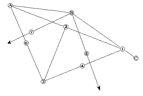
My solution makes use of the following sketch diagram (not drawn accurately):

Units A, B, and C are frontline units; we are considering the rear area of unit B. We first calculate Point 1, the point on the line connecting B with C that is as far from B as A is from B. This makes triangle A, B, Point 1 an isosceles triangle. We then calculate the midpoint of the baseline, Point 2. This is easily done by averaging the coordinates of A and Point 1.
Now comes a cute trick: the perpendicular to a line is easily calculated by taking the negative inverse of its slope. This allows us to calculate the perpendicular to the line Point1 - Point 2. The significance of this perpendicular is that it points towards the rear of Unit B. Now, we could get very messy here with the problem of getting our perpendicular to pass through Point 2. It would involve the equation for a line with a given slope passing through a given point, and would be ugly. Fortunately, we don’t need the full-blown equation; all we need is a single point, Point 3. For reasons to be seen later, we desire this point to fall on the perpendicular at a distance equal to the distance Point 1 - Point 2. Rather than belabor the arguement, I shall simply show you the code to calculate Point 3:
DX := X2 - X1;
DY := Y2 - Y1;
IF ((DX>0) & (DY>0)) OR ((DX<0) & (DY<0)) THEN
BEGIN
DX := -DX;
DY := -DY;
END;
X3 := X2 - DY;
Y3 := Y2 - DX;
In this code fragment, I use "X#" to refer to the x-coordinate of the #th point, and similarly for Y. DX and DY refer to delta-X and delta-Y.
Note that the negative inversion of the slope is handled by reversing and negating the coordinates in the last two lines of the code fragment.
Now that we have Point 3, things get easy. Point 3 forms two isosceles triangles: A - Point 2 - Point 3; and Point 1 - Point 2 - Point 3. I shall begin with the latter triangle. We can bisect the segment Point 1 - Point 3 by averaging their coordinates; this yields Point 4. Since the triangle is an isosceles right triangle, the line Point 2 - Point 4 lies at 45 degrees to line Point 2 - Point 3. Unfortunately, Point 4 is not quite what we need, as it yields a line based on Point 2, and Point 2 is displaced from Unit B. This is easily corrected by creating Point 5, a point displaced from Point 4 by exactly the amount that Unit B is displaced from Point 2. This means that the line Unit B - Point 5 runs 45 degrees out from the line to Unit B’s rear.
A similar calculation yields Point 6 and Point 7. With the two 45 degree lines produced by these computations, we can define a triangular region bounded by these lines as the rear area of Unit B. Any enemy unit placed in this area constitutes a threat to Unit B. To determine whether an enemy unit falls inside this region, we perform some analytic geometry:
AX := XB - X5;
AY := YB - Y5;
BX := XEnemy - XB;
BY := YEnemy - YB;
CX := X7 - XB;
CY := Y7 - YB;
DX := XEnemy - X7;
DY := YEnemy - Y7;
IF (((AX * BY) - (AY * BX)) < 0) AND
(((CX * DY) - (CY * DX)) < 0) THEN
BEGIN
{Yes, he is behind us!}
This last IF-statement makes use of the equations for the two lines. The inequalities express the notion that the tested point falls on a particular side of a line.
Conclusions
The point of this rather tedious exercise is that it is possible to use analytic geometry to tackle some apparently difficult problems in wargame AI. The analytic geometry approach may not be simple, but it does yield good results.
